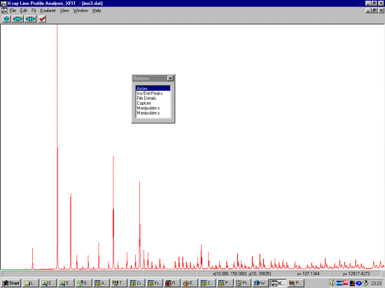
Also, if you do have a floating Options menu, select Edit, Show Options to bring this up.

Why Bother?In the following example, we are going to go through what it takes to fit parts of a laboratory diffractometer using the fundamental parameters approach. This uses the geometry of the diffractometer as well as other information to model the contribution to the peak profiles, leaving the size and strain to be refined. This is very stable and requires less refinable parameters.Other annoyances with other methods are such things as low and high angle peak asymmetry (the low angle peak asymmetry being primarily due to axial divergence of the X-ray beam; and the high angle peak asymmetry being due to penetration depth of the X-ray beam). XFIT handles this as part of the machine geometry without the need for releasing extra parameters. However, the geometry, slit system, and tube type have to be defined correctly. This In2O3 data was obtained from Armel Le Bail's Powbase website at http://sdpd.univ-lemans.fr/powbase/. The In2O3 data can be downloaded here in XFIT DAT format if you have problems with the above database. The data was collected with a Bruker goniometer (205mm goniometer radius) with Cu LFF X-ray tube, incident and diffracted beam Sollers slits with 2 degree acceptance angles, Automatic Divergence Slit subtending a 6mm constant illumination of the sample surface, 0.1mm receiving slit, diffracted beam graphite monochromator; and 6mm slit widths. |
|
Run XFIT, (maximise the screen if you wish)
and do File, Load Data and open
the in2o3.dat dataset. You can maximize the data to
fit the entire XFIT screen. It should look something like
the following. (if you can't see the active mouse output on
the bottom right of the XFIT screen - maximise your XFIT
window).
Also, if you do have a floating Options menu, select Edit, Show Options to bring this up.
|
|
You may wish to use the T key to zoom up and reveal the trace
peaks you will also want to fit. Also, for the purposes of this tutorial,
we will only want to fit up to 71 degrees 2-theta. (use the left and
right arrow key to zoom on the 2-theta axis).
|
|
Within the Options Box, click on Ins/Del Peaks option to
bring up the Peak Edit Options box. If you started XFIT,
the FP (fundamental Parameters) peak type is the default peak type.
Insert peaks only on the left hand/lower angle CuK alpha peaks. The CuK beta peak will be automatically fitted when we assign the lambda files.
|
|
In the options box, select File Details to bring up the File Details menu. Select Assign LAMs to Files (3rd from the top). Click below the Assign LAM Files to the right of the y2o3.dat file so that you bring up the Assign option in the Options area. Then click on the Assign option in the Options area to bring up the browse box, and go to the c:\koalarie directory and assign/load the Cuka_2.lam. This describes the emission spectrum for the Copper K Alpha1 and Alpha2
|
|
The background on this particular sample is not nicely linear so we should allow to polynomial fitting of the background a bit more flexibility. Still in the File Details menu, enter Bkg Parameters and set the Polynomial Order to 5.
|
|
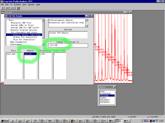
Warning: When doing the following, you have to remember that it is not enough to just set the value of a parameter in the Value area, but you must also tell the program that you wish to Use this parameter in the Use menu area. (this is a nuance of the XFIT program) Still in File Details go down to the Fit Const and Stats, Radius, Relax Conv.Step to define the diffractometer radius. This Bruker diffractometer has a goniometer radius of 215mm. To change a parameter, double click on the value, modify it in the Change Selections To box and press enter. This is automatically used so there is no need to set a Use flag.

|
|
While still in the File Details go down to the Instrument, Values to define the diffractometer geometry and tell the program to use the relevant parameters. (If you use the method of saving to templates - you would only have to do this once for your diffractometer). The parameters to insert here are as follows (and the value for this setting of the Philips diffractometer). To change the value of a parameter, double click on the value, modify it in the Change Selections To box and press enter.
Now go into the Use option and select use for SW (Receiving Slit), FSFL (Irradiated length of the sample) and TARGET
|
|
Again, while still in the File Details go down to the Axial Divergence, Values to define the diffractometer geometry. The parameters to insert here are as follows (and the value for this setting of the Bruker diffractometer).
Now go into the Use option and select use for all the above parameters.
(If you wanted to insert a linear absorption coefficient, stay in File Details go to the Axial Divergence, Values to define the diffractometer geometry. The parameters to insert here are as follows (and the value for this setting of the sample). In this case, we will leave it unused. Even though there is a value inserted here - if set to Not Use, it will not be applied to the profiles.) |
|
Now we must tell the program that we wish to Use the peaks we selected near the top of this tutorial. While still in File Details, near the bottom of the menu, select Peaks, Fundamental Parameters Peaks, Use. File Details, Peaks, Fundamental Parameters Peaks, Use.
Highlight all the Cr Size values and set to Use (clicking on the "Cr. Size" text will "select all" peaks)
Highlight all the Strain values and set to Use
By default, the strain values are set to 0 - which is not a legal value for XFIT to handle. Set all the strain values to 0.01. To do this, highlight all the values, insert 0.01 in the Change Selections To box and press enter.
|
|
At this point, if the peaks belonged to the same phase, you could constrain all the peaks to have the same crystallite size and strain. The advantage of doing this is that only two independent parameters are refined per peak (position and intensity). Yttrium Oxide has a reputation of being a good intensity and size/strain standard so we can constrain all the peaks to have the same crystallite size and strain for the moment. Thus refine all the peaks using the same crystallite size parameters and identical crystallite strain parameters. To do this, highlight all the values, click in the Change Selections To and type in the name of "a" codeword. In this case, we will use the word cry (though we could use any arbitrary word). Note that the peak Area and position (Th2) have a @ value. This means they will refine separately (which is the normal thing) but they can be fixed or constrained as we are doing with the crystallite size and strain.
Refine all the peaks with strain using the same crystallite strain for each peak. To do this, highlight all the values, click in the Change Selections To and type in the name of "a" codeword. In this case, we will use the word strain (though we could use any arbitrary word).
|
|
Select the plot window and from the top menu bar, select Fit, Fit Marqardt. This brings up Fit Details box. You have the option to step through the fitting cycles one at a time. You can stop on the next cycle - and keep all the information refined up to that point.
Click on the Start to start the peak refinement. This can go rather quickly and when the refinement converges, you will get a Refinement converged prompt. Press OK and then Yes to keep the Refined parameters. Notice how the CuK alpha 2 is automatically fitted due to how we assigned the appropriate LAM file. Also, the problem with the tails on the very intense peaks could be due to i) incorrect input of XRD geometry parameters and/or ii) a type of size distribution that the Fundamental parameters equations are not modelling correctly and/or iii) that not enough "half-widths" are being calculated byt the software (not sure if this can be modified in XFIT?).
|
|
In File Details, Peaks, Fundamental Parameters Peaks, Values, Clicking on Create TXT Report will put these into an ASCII file that can then be saved or copied using [CNTRL] C. You can also use File, Save Project As to save your work for future reference or to use the fit as a template for other similar files. Note how the crystallite sizes are all identical and the strain is all identical.
|
|
While the plot window is selecting, typing A from the keyboard to view full scale on the Y-axis.
|